|
ELECTRICAL |
|
|
As I've mentioned elsewhere, I fully intended to install the electrical, cooling and fuel systems necessary for my swap into the car while still running the stock drivetrain. It seemed like a way to approach a large project incrementally -- in terms of time and expense -- while minimizing the time the car was off the road. Ultimately, I was sucessful with the cooling system, got part of the way with the electrical and did nothing about the fuel before pulling the engine. My "part way" move with the electrical system was to take the main fusebox and main power leads (battery, alternator and starter) and mount them into the Datsun. This was pretty easy, just a short afternoon's work. The bonus to doing this was that the Miata has the battery in the back, so my otherwise stock Roadster had a rear-mount battery solution. Unfortunately, I pulled all sorts of "unnecessary" leads out of the guts of the main Miata fuse box, only to discover that they were not only necessary, but also documented solely in the $100 factory manual. After it was clear that I not only had no idea where things went, and had lost some of the OEM patch wires, I bought second, intact fuse box and started over with it. Even with a complete box, figuring out what wires went where (e.g. directly to relays, to the in-cabin fuse box, directly to sensors/actuators, to the ECU, etc.) took a fair amount of time, patience and flipping through 15 or so pages of half-assed Mitchell program Miata wiring diagrams. So far, I have created my own wiring diagrams for the ECU (stripped of unnecessary wires, mostly having to do with smog and safety devices) and the power circuit. I still need to finish the diagram that shows how the new Miata wires (including a retrofitted Miata cabin fusebox) mesh with the Roadster's non-powertrain-related wiring (lights, gauges and eventual audio). This, is really only a matter of redrawing how things connect with the new fuse box and making note of some other aspects of my non-stock harness, which I created about 2 years ago. |
|
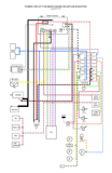 |
This is my power harness diagram, based on the stock Miata fuseboxes, but stripped of any leads unnecessary to running the engine in the Datsun (stripped of smog devices, power assist devices and A/C). [UPDATED 6/8/16: redrawn to reflect upgraded wiring harness]
|
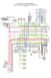 |
Here is the ECU harness diagram based on a '94 Miata harness with 5-speed, with all smog devices removed. So far, I've gotten the check engine light to give me some error codes, about the missing smog equipment, but it starts and runs fine. [UPDATED 6/8/16: redrawn to reflect upgraded wiring harness]
|
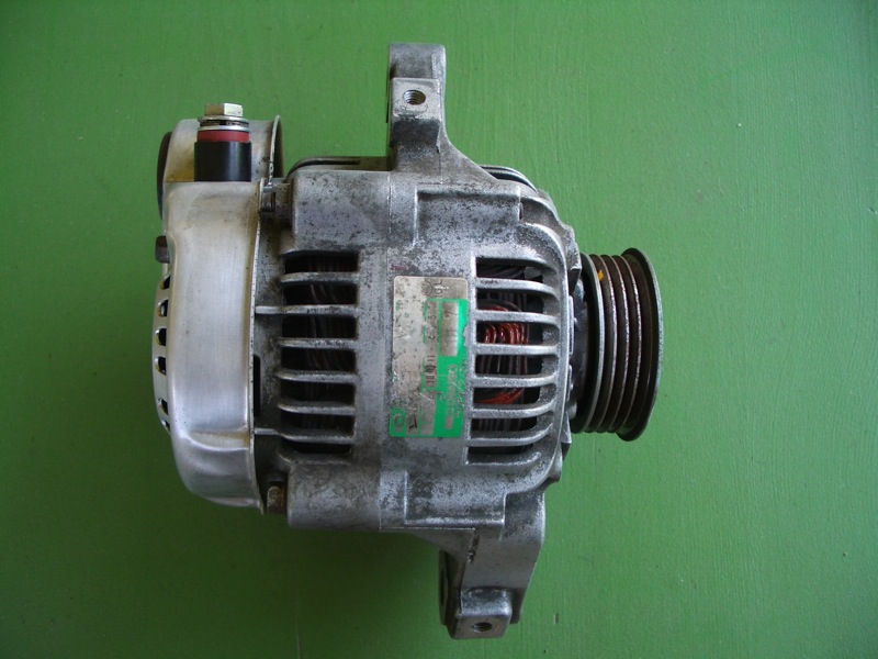 |
The alternator is a Nippon-Denso unit #8172. This is the smallest OEM automotive alternator available. It was stock on 3-cylinder cars, such as the Diahatsu Charade and Chevy / Suzuki Sprint / Swift. No other alternator will fit between block and framerail.
|
 |
Even so, I had to clock the rear housing 90-degrees so that the power terminal would face up. In stock form, it would point to the left in this photograph, which makes it bang right into the frame. Clocking required disassembling the *entire* alternator. A lot of work.
|
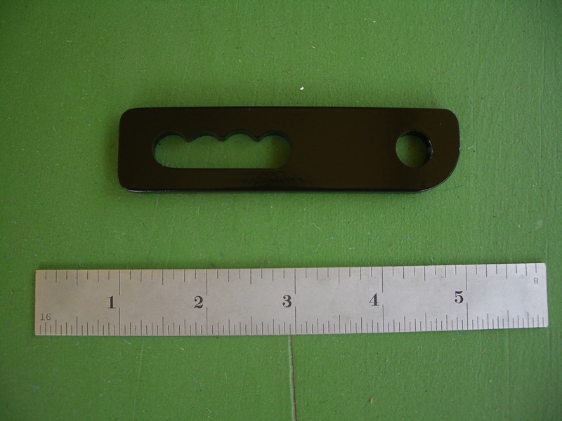 |
This bracket is so short that I felt comfortable using 1/4" steel to make it. I left the upper ridges from the drill-based slotting because I thought they looked kinda cool.
|
 |
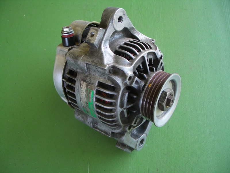
Here is a picture of the alternator installed. The belt is a Goodyear #4040342, as it is 34.25" in circumferance. The pulley comes from a Subaru Justy, which gives the 4-rib pattern that matches the Miata. Take the nut from the Justy and it will all fit together real well.
|
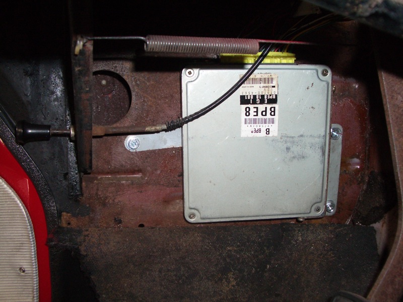 |
Here is an image of the ECU mounted along the driver's side kick panel. I simply drilled three holes and used really big sheet metal screws. (The only modifications to the Datsun itself in the entire build.) This placement allows me to use the Miata ECU harness as my entire engine harness; the wires reach from here all the way to the MAF sensor in the far front of the engine bay.
|
 |
The Miata has a nice relay rack mounted on the driver's side fender. I didn't want to see it, though, so I modified it to mount in the Datsun's factory mono radio speaker holes high up in the passenger footwell. First I cut the mounting tabs off of the rack itself, and drilled a 3/16" hole at each end.
|
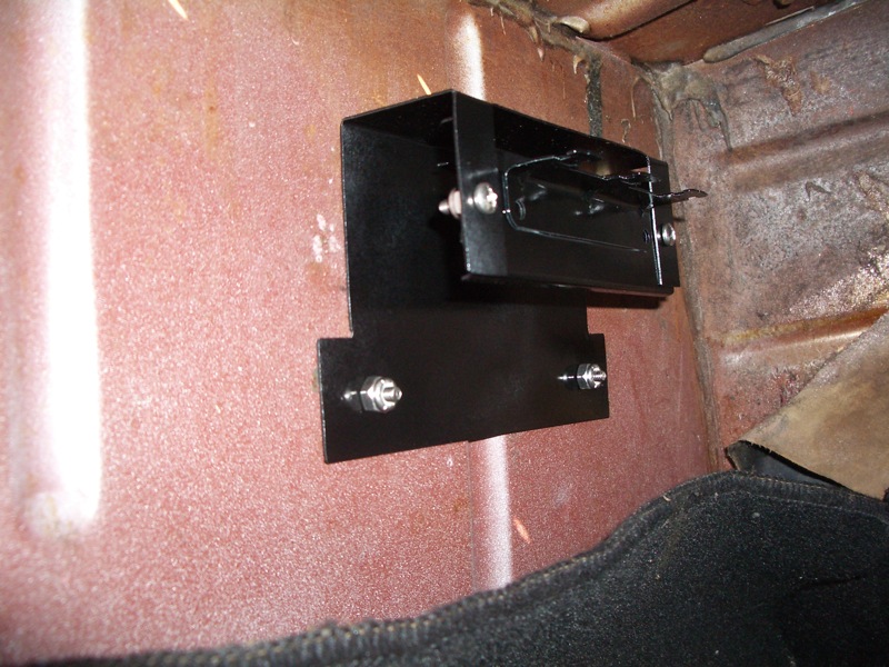 |
Then, I cut and folded a simple bracket to join the rack to the pre-existing holes in the footwell. I used 22-gauge steel because I had an odd-shaped piece laying around. It's a little flimsy; 18- or 16-gauge might be better. When sitting in the car, you really have to tip yourself flat against the transmission tunnel to see this thing.
|
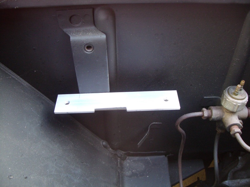 |
This little bracket, made from 1"x1" aluminum angle stock, mounts the Miata's main fuse box to the lower mount hole for the coil bracket on the Datsun. I threaded the two holes you see at 1/4-20 since holding a nut under there would be a real hassle. Note the notch for a bulge in the back of the fusebox.
|
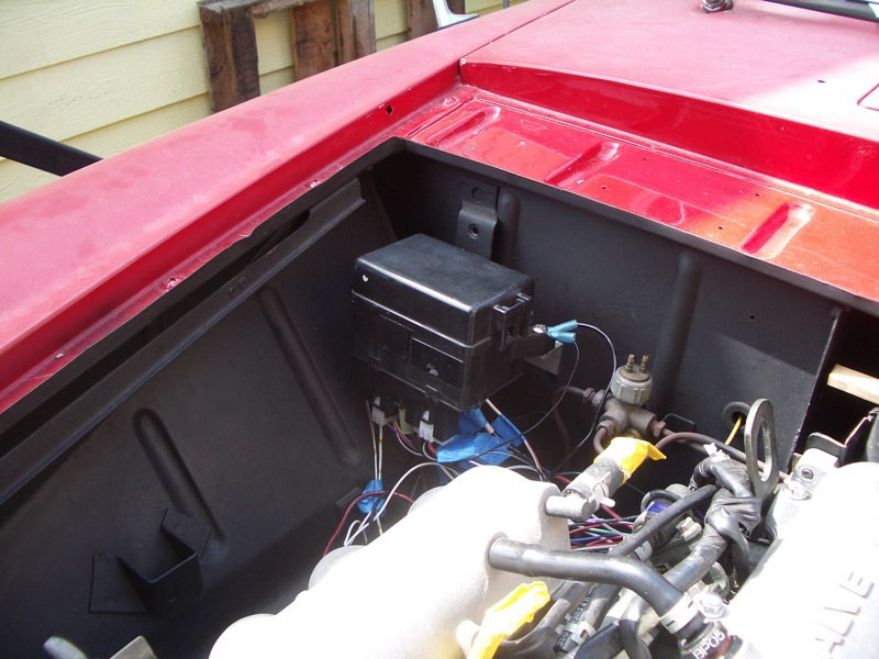 |
The main fuse box looks rather nice and tidy tucked away in the corner, I think. Never mind all the stray wires; I'll tidy them up as soon as I know that the thing runs.
|
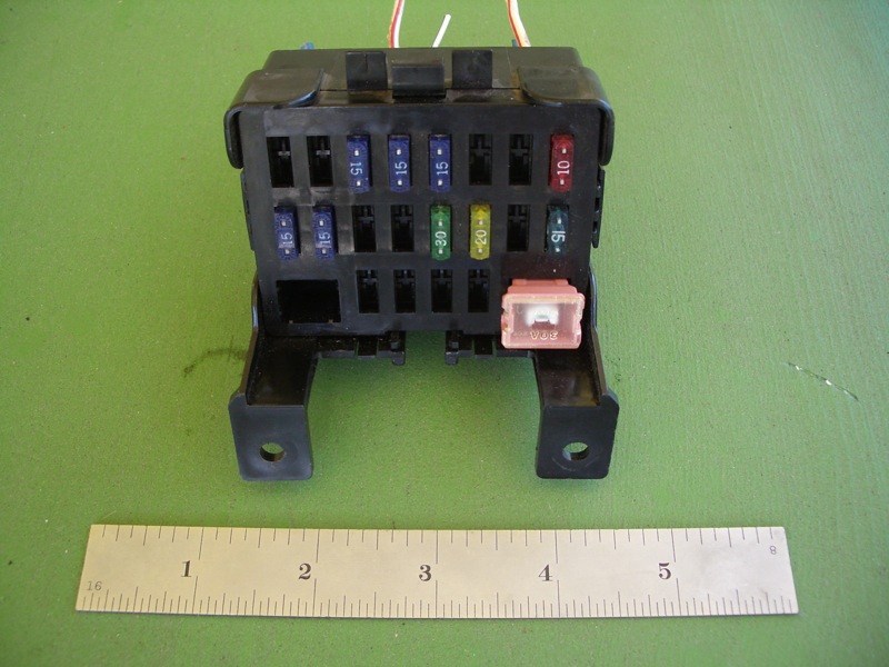 |
Early on in the swap preparation, I pulled the room fusebox from a '96 Miata. I liked its compactness. At first I wired it up with a bunch of pigtails, but finally in 2016 I found a power terminal that I could modify to fit into this box so that I could crimp and run complete wires (and also rearrange the circuits to make more sense in the box).
|
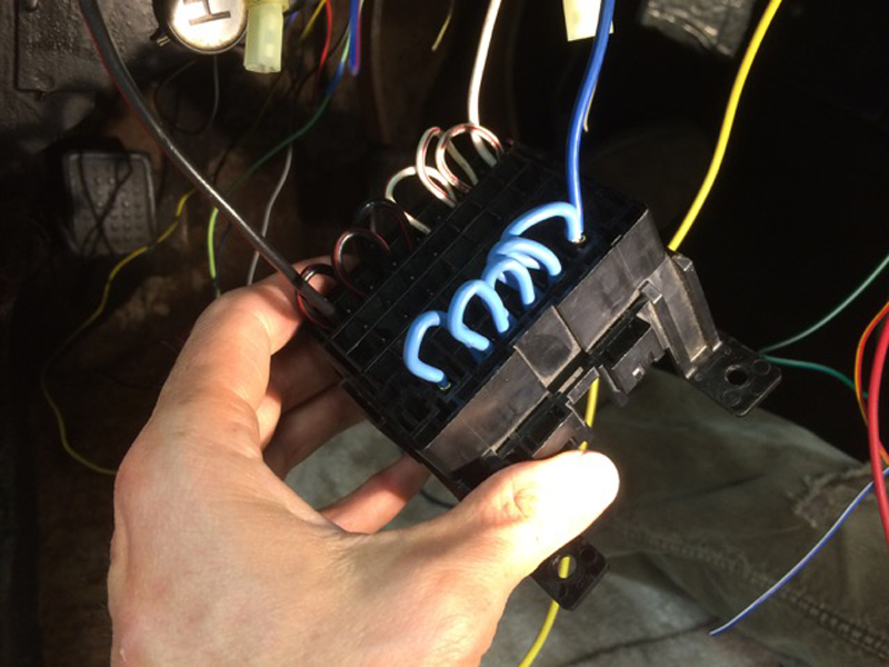 |
So, for my revised version of this fusebox I bought Junior Timer Power female terminals in several gauges from Ballenger Motorsports. I then modified them slightly with a rotary tool, and they slip into the fusebox slots and lock nicely.
|
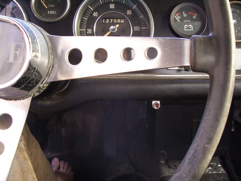 |
Since I have a '94 engine, it's OBD-I, so my diagnostic options are limited. I have a small Radio Shack LED under the dash that used to be my "fan is on" light & now runs to the "check engine" light lead on the ECU. [Removed in 2016 because I never used it.]
|
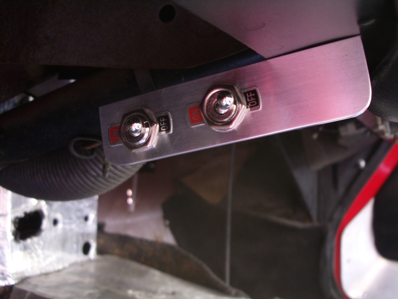 |
These two switches, to the left of the steering column, under the dash, allow me to diagnose: one grounds the "TEN" (test engine) lead from the ECU, which causes the check engine light to blink stored codes. The other activates the brake switch lead to the ECU, which is used to clear stored trouble codes. [Removed in 2016 because I never used it.]
|
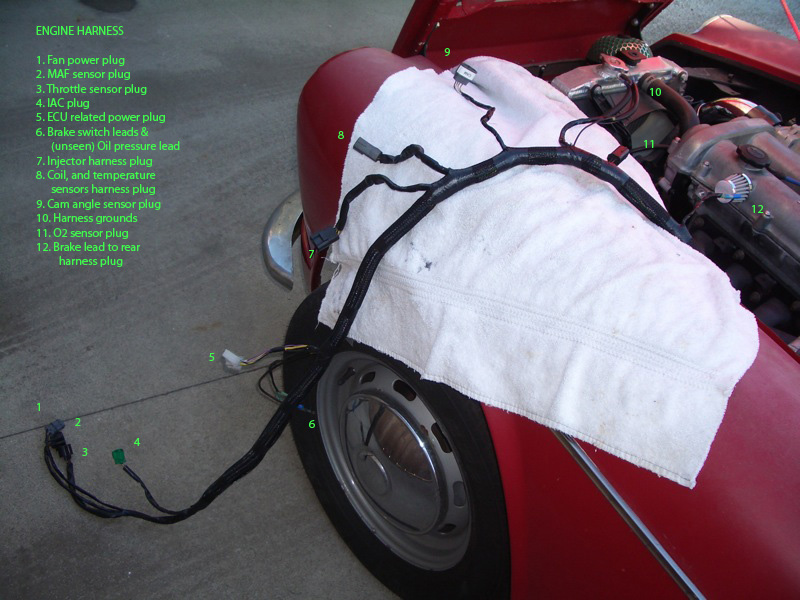 |
Here is a view of the final, wrapped engine harness before installation. I included the oil pressure lead, the brake leads and the (gauge) coolant temperature lead in this harness, as well as ECU-related power leads. There is a separate harness for the general power leads, not shown. Click on the image to see the pig tails labelled.
|